Generation of an icosahedron by the intersection of five tetrahedra:
geometrical and crystallographic features of the intermediate polyhedra
Livio Zefiro
Dip.Te.Ris, Universita' di Genova, Italy
Notes
tested with Internet Explorer 6, Mozilla Firefox 2 and Opera
9.22 at 1024x768 and 1280x1024 pixels
many of the images have been realized by SHAPE 7.0,
a software program for drawing the morphology of crystals, distributed by Shape Software
hovering with the mouse on the images, sometimes the
symbol of a pointer appears: if your web browser is set up to visualize VRML
(Virtual Reality Modeling Language) files, by clicking with the left button of
the mouse it should be possible to visualize in a new window the corresponding dynamic image, that can be enlarged, rotated, shifted...
A good Web3D visualizer can be downloaded from here. |
Introduction
It is well known that an icosahedron can be decomposed into five groups
of four faces such that the faces belonging to each group have the same orientation of the faces of a tetrahedron.
The reciprocal procedure implies that, starting from a tetrahedron,
the stepwise addition of other four tetrahedra, properly orientated, leads to icosahedron,
through the intermediate polyhedra obtained by the intersection of compound polyhedra made of two, three and four tetrahedra,
respectively.
The orientation of each compound polyhedron made of n
tetrahedra depends on the orientation of the constituting tetrahedra, but one
can recognize, by proper rotations, the congruence of all the 5!/[(5-n)! n!]
compound polyhedra made of n tetrahedra. The same thing
occurs with their intersections, so that, after iso-orientation, the polyhedra intermediate between
tetrahedron (43m
crystallographic point group) and icosahedron (m35 point group)
can be compared and their symmetry easily identified: whereas in the intersection of both two and three tetrahedra
the symmetry is trigonal (32 point group), in the intersection of four tetrahedra
the symmetry is cubic (23 point group).
(clicking on the following images one can visualize the corresponding VRML files)
Due to the lack of mirrors and inversion centre, such intermediate polyhedra can exist in enantiomorphic (or
chiral) forms, whereas the icosahedron, with its fifteen mirrors and an inversion centre, admits only the possibility
of a chiral colouring. On the other hand, enantiomorphism characterizes all the compound polyhedra made of tetrahedra,
included the one made of five tetrahedra.
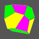
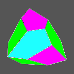
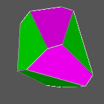
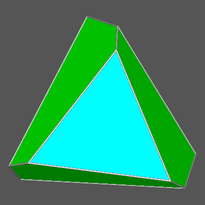
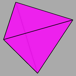
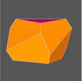
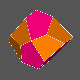
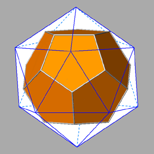
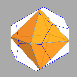
A particular interest is incidental to the polyhedron corresponding to the intersection of four tetrahedra,
named tetrahedrally stellated icosahedron by
George W. Hart; its dual, consisting in the truncation of four out of twenty vertices of a regular dodecahedron,
can be analogously named tetrahedrally truncated dodecahedron.
(clicking on the following images one can visualize the corresponding VRML files)
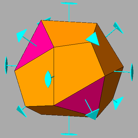 |
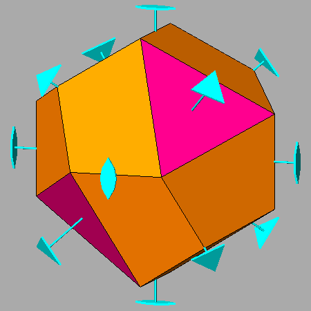 |
| Tetrahedrally stellated icosahedron (on the left) and its dual, the tetrahedrally truncated dodecahedron (on the right).
Also the axes of rotation (three 2-fold and four 3-fold axes), common to both polyhedra, are reported. |
�
From tetrahedron to icosahedron
The five convex regular polyhedra (or
Platonic solids), divided into polyhedra with cubic symmetry ( cube, tetrahedron
and octahedron)
and icosahedral symmetry ( icosahedron and dodecahedron), can be correlated in different ways:
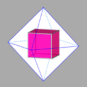
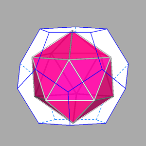
Each is inscribable in another, according, for istance, to the following
sequence:
icosahedron - octahedron - tetrahedron - cube - dodecahedron
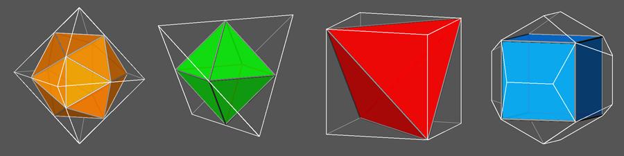 |
|
From left to right:
icosahedron inscribed in an octahedron
octahedron inscribed in a tetrahedron
tetrahedron inscribed in a cube
cube inscribed in a dodecahedron
|
Also, the polyhedra belonging to the dual couples cube-octahedron and dodecahedron-icosahedron are
reciprocally inscribable, This is a consequence of their duality; the fifth
Platonic solid, the tetrahedron,
is inscribable in another tetrahedron, being autodual.
Concerning the other combinations of polyhedra, it is worth mentioning both the
octahedron inscribed in dodecahedron and the
icosahedron inscribed in
cube.
Using the pleasing notation
proposed by John Conway, tetrahedron is linked by the operators named join, ambo, gyro and snub
to the other four Platonic solids (cube, octahedron, dodecahedron and
icosahedron, respectively).
|
|
Conway operators linking the tetrahedron to the other four Platonic solids. |
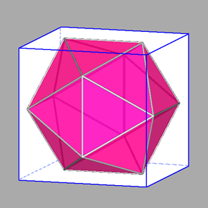
A further relation between the two platonic solids having the
least and the maximum number of faces is given from the possibily to generate
an icosahedron by the intersection of five tetrahedra having their faces
orientated like the icosahedral ones.
|
|
Animated gif showing the orientation of the five tetrahedra with rispect to icosahedron and, step by step,
the result of their addition leading to a 5-colored icosahedron.
|
The procedure leading from tetrahedron to icosahedron (already
described
here) can be summarized as follows.
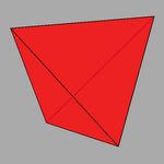
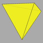
The starting point is a tetrahedron whose faces have the Miller indices:
(111), ( 11 1),
( 1 1 1),
( 1 1 1).
The choice, as second tetrahedron, of the one whose faces are characterized by the indices:
( 1 1 1),
(1 11), ( 111), (11 1),
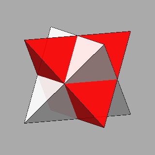
hence placed centrosymmetrically with respect to the faces of the first tetrahedron, would
lead to a compound polyhedron named stella octangula by Kepler. It can
be regarded as the stellation of the octahedron resulting from the intersection of the two previous tetrahedra.
(clicking on the following images one can visualize the corresponding VRML files)
Such choice of the second tetrahedron is not suitable to reconstruct an
icosahedron from tetrahedra, since the remaining
twelve faces of the icosahedron could not be distributed among the three other
tetrahedra with faces orientated as the icosahedral ones. Nevertheless, each of the four
other tetrahedra that are fit to reconstruct the icosahedron can be derived
just from this "forbidden" tetrahedron by a rotation of 44.48� around the direction
perpendicular to one of its faces: this implies that the other three faces of each
tetrahedron, making an angle of 109.46� with the first face, undergo a rotation of 41.81� (corresponding to the angle
between the perpendiculars to every pair of contiguous icosahedral faces).
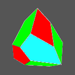
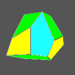
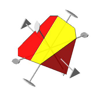
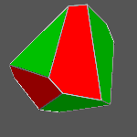
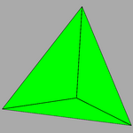
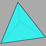
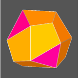
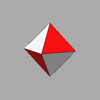
In the following image one can see, in
their own orientations, the four tetrahedra obtained, by the described
procedure, starting from the "forbidden" grey tetrahedron (in the centre);
their faces, and the faces of the red tetrahedron, result to be orientated like the twenty icosahedral faces.
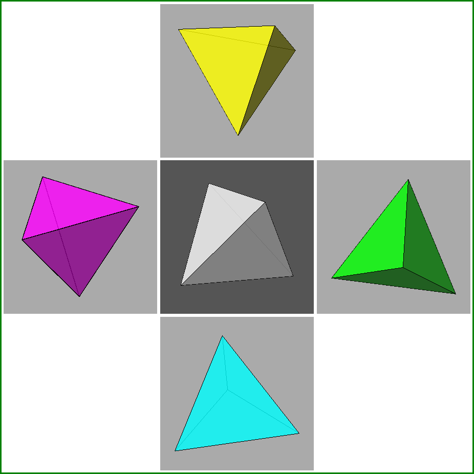 |
Four coloured tetrahedra, in their own orientation, obtained from the "forbidden" one (in grey, at the centre of the image):
with the addition of the red tetrahedron, their intersection corresponds to an icosahedron.
|
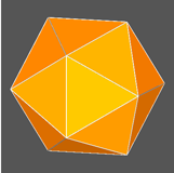
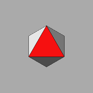
The next view of the icosahedron along the [111] direction evidences the yellow
faces involved in the rotation of the "forbidden" tetrahedron.
(clicking on the following image one can visualize the corresponding VRML file)
|
Animated view of an icosahedron along the [111] axis (perpendicular to a face
deriving from the red tetrahedron). The dark-grey and yellow icosahedral faces are involved in the procedure,
described in the text, that has been applied in order to orientate properly the second tetrahedron;
each icosahedral face derived from the yellow tetrahedron can be obtained also by a rotation of 41.81�
of the contiguous dark-grey face, derived from the "forbidden" tetrahedron,
around the edge shared by the two faces.
|
There is an alternative method that permits to obtain
a second tetrahedra starting from the red one. The stereographic projection of the rotation axes
of icosahedron, described in a previous work concerning
icosahedral polyhedra, lets one ascertain that there are three 2-fold axes
perpendicular to every 3-fold axis present in icosahedral forms. In particular, the three 2-fold axes
perpendicular to the [111] axis (and therefore parallel to the [111] face of the
red tetrahedron) have the irrational indices: [1
-1/τ τ], [-1/τ τ 1],
[τ 1 -1/τ ] where τ = (√5+1)/2
=1.61803... denotes the golden ratio: by rotating the faces of red tetrahedron around each of the 2-fold axes, one
directly obtains the faces of the yellow tetrahedron.
It must be pointed out that these 2-fold axes are not symmetry operators of tetrahedron, just as it happens during the process of crystal twinning.
|
 |
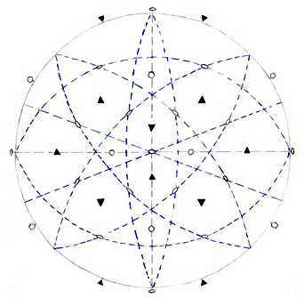
a) Stereographic projection of the icosahedral
rotation axes, including the drawing of the zones of 3-fold axes: three 2-fold axes
belong to each zone.
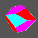
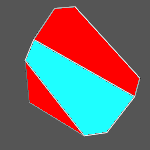
b) view along [001] of the polyhedron resulting from the intersection of {111}
red and {111} yellow tetrahedra,
reporting also the three 2-fold axes perpendicular to the 3-fold axis directed along [111].
The relative VRML image is visible clicking
here. | |
In the next table one can see that each 2-fold axis of
rotation correlates four different pairs of faces made of a red and a yellow face.
|
Directions of 2-fold axes correlating pairs of faces belonging to
red and yellow tetrahedra |
| |
(1
1 1) |
(1 1
1) |
(1 1
1) |
(1 1 1) |
|
(τ -1/τ 0) |
[-1/τ τ 1] |
[1
-1/τ τ] |
[τ 1
-1/τ] |
- |
|
(0
τ -1/τ) |
[τ 1
-1/τ] |
[-1/τ τ 1] |
[1
-1/τ τ] |
- |
|
(-1/τ 0 τ ) |
[1
-1/τ τ] |
[τ
1 -1/τ] |
[-1/τ τ 1] |
- |
|
(1
1
1) |
- |
- |
- |
[-1/τ τ 1]
[1
-1/τ τ]
[τ 1
-1/τ]
|
|
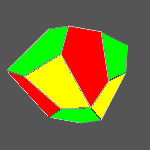
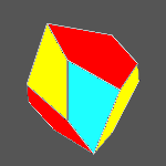
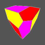
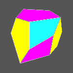
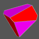
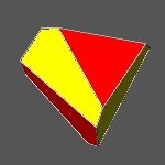
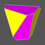
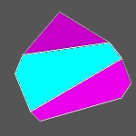
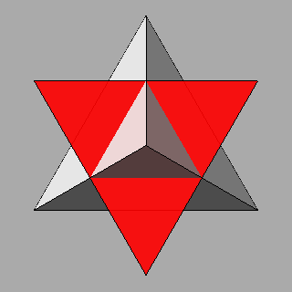
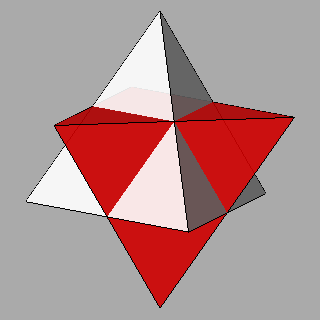
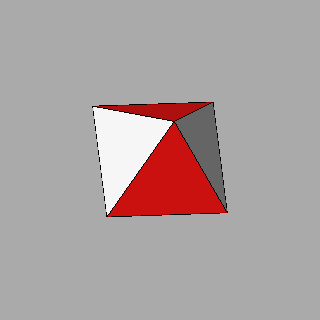
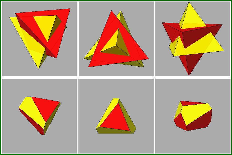
Views, along different directions, both of the compound
polyhedron made of red and yellow tetrahedra (make a comparison with stella octangula) and the polyhedron
resulting from the intersection of the two tetrahedra. |
The following tables show the single steps leading from tetrahedron to icosahedron
through intermediate polyhedra deriving from the intersection of two, three and four polyhedra.
In the first table of the series one can see the ten polyhedra
deriving from all the possible pairs of tetrahedra: also the indices of all the tetrahedral faces are reported.
(clicking on the images one can visualize the corresponding VRML files)
Congruent polyhedra corresponding to the intersection of pairs of tetrahedra
that originate from the decomposition of an icosahedron into five tetrahedra |
| |
|
1st
tetrahedron |
| |
Indices
of each
tetrahedral
face |
(1 1 1)
( τ 1/τ 0)
(0 τ -1/τ)
(1/τ 0 τ)
|
( 1 1 1)
(τ 1/τ 0)
(0 τ 1/τ)
(-1/τ 0 τ ) |
(1 1 1)
( τ
-1/τ 0)
(0 τ 1/τ )
(1/τ 0 τ )
|
( 1
1 1)
(τ -1/τ 0)
(0 τ -1/τ)
(-1/τ 0 τ) |
(1 1 1)
(1 1 1)
(1 1
1)
(1
1 1) |
|
2nd
t
e
t
r
a
h
e
d
r
o
n
|
(1 1 1)
(1 1 1)
(1 1
1)
(1
1 1) |
 |
 |
 |
 |
 |
( 1 1 1 )
(τ -1/τ 0)
(0 τ -1/τ)
(-1/τ 0 τ) |
 |
 |
 |
 |
|
(1 1 1)
( τ
-1/τ 0)
(0 τ 1/τ )
(1/τ 0 τ )
|
 |
 |
 |
|
( 1 1 1)
(τ 1/τ 0)
(0 τ 1/τ)
(-1/τ 0 τ ) |
 |
 |
|
(1 1 1)
( τ 1/τ 0)
(0 τ -1/τ)
(1/τ 0 τ)
|
 |
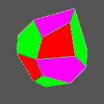
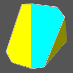
It is not difficult to realize that the previous polyhedra, made of pair of tetrahedra,
are all congruent (regardless of colouring),
as visualized by the animated gif images contained in the following table relative to compound polyhedra,
deriving from the combination of the red tetrahedron with the four others,
and their intersections: starting from every initial orientation of the different couples of tetrahedra,
by appropriate rotations a final common orientation is obtained in every case.
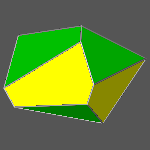
In the same way, ten congruent sets of three tetrahedra can be obtained adding a third tetrahedron
to the previous pairs of tetrahedra.
(clicking on the images one can visualize the corresponding VRML files)
|
Congruent intersections of three tetrahedra obtained by the addition
of a third tetrahedron to each pair of tetrahedra |
| 

 In the same way, ten congruent sets of three tetrahedra can be obtained adding a third tetrahedron
to the previous pairs of tetrahedra.
In the same way, ten congruent sets of three tetrahedra can be obtained adding a third tetrahedron
to the previous pairs of tetrahedra.