|
Department of Mathematics Centenary College of Louisiana
IntroductionConsider the two designs seen in Figure 1. The design on the left is inspired by creations of the Chokwe people of Africa, while the design on the right is of Celtic origin. Both designs can be traced in one smooth continuous motion without lifting one's finger. Moreover, both designs appear to be based on an underlying rectangular grid. 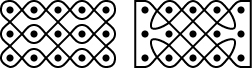
Figure 1: Celtic and Chokwe mirror curves The goal of this paper is to explore how designs of this type can be created. In particular, we will show how both of the above designs can be thought of as mirror curves and outline conditions on when the designs cannot be traced in a single motion. Mirror CurvesOur definition of mirror curves follows the definitions of Slavik Jablan [2]. To start, we define a mirror box to be a rectangle in the plane with corners at (0,0), (2n,0), (0,2m), and (2n,2m) for m,nÎN. (We will refer to the dimension of the box by calling it an m by n mirror box.) Next, we create an m by n rectangular array of dots within the box at points (h,k) where h and k are odd numbers less than, respectively, 2n and 2m. A mirror may be placed at any location (h,k) within the box as long as either h or k is even (but not both). In other words, mirrors are between pairs of dots. Mirrors have either horizontal or vertical orientation. Figure 2 shows a typical mirror box with some mirrors in the next to last column of the array. 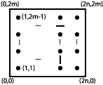
Figure 2: A mirror box with mirrors Once the mirrors have been placed within the box, we will refer to the box and mirrors as a mirror plan. Note that we are assuming that the underlying grid is rectangular. Jablan [2] discusses mirror boxes built on a wider class of shapes. Christian Mercat, in his tutorial on Celtic knots [3], also discusses a method of construction similar to mirror boxes on nonrectangular grids. Next, we tile the mirror plan with squares of length 2 whose vertices have even integer coordinates. We then create a graph where the vertices are the midpoints of the sides of the squares and the edges form a subset of all the line segments connecting the midpoints of adjacent sides. A mirror curve is a cycle in this graph with the property that the direction of travel only changes at mirrors or at the sides of the box. If the mirror curve is contained inside an m by n mirror box, we call the curve an m by n mirror curve. Figure 3 shows a mirror plan with no mirrors, the tiling of the interior, and a sample 2 by 4 mirror curve. For the sake of clarity, we will draw mirror curves with rounded corners from now on. 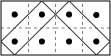
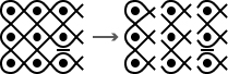
Figure 3: A mirror curve in a mirror box In Figure 4, we have created the mirror plans for the mirror curves shown in Figure 1. Note that the curves are completely determined by the number, location, and orientation of the mirrors. 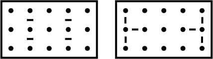
Figure 4: Mirror Plans Depending on the placement of mirrors, a mirror curve may not necessarily include all the line segments connecting adjacent sides. (Figure 3 shows an example.) In that case, additional mirror curves can be drawn within the shape. The union of all the possible mirror curves within the mirror box will be called a mirror curve design. Our goal, however, is to place mirrors to ensure that the design is monolinear, that is, that the mirror curve design consists of only one mirror curve. There is one well-known result on monlinearity. Theorem 1: Given an m by n mirror box with no additional mirrors, the associated mirror curve design consists of gcd(m,n) mirror curves. In particular, the mirror curve design is mononlinear if and only if m and n are relatively prime. Two different proofs of this theorem can be found in an
paper [4] by the author and in work by Gwen Fisher and
Blake Mellor [1]. In our next section, we will determine
conditions on monolinearity for a small class of mirror plans.
The 3 row caseFor the rest of the paper, we make the following three assumptions: 1) all mirrors are horizontal, 2) no mirrors are located in the first or last column of the design, and 3) mirrors only occur between vertical pairs of dots. Note that all three assumptions are violated by the Celtic design, but are satisfied by the Chowke design. Moreover, to ease the introduction of concepts, for this section we will only look at 3 by n mirror designs. Our general approach will be to analyze the design column by column (as shown in Figure 5). We will think of building the design by adding columns from left to right. We will develop machinery that will associate with each column the number of mirror curves in the design if the design ended after that column. Note that each column contains six strands that form a braid. We will associate each column with a graph (denoted a mirror graph) that represents which strands are connected to each other when all columns up to the current one have been added to the design. Each interior column will also have an associated mirror permutation that describes how the strands change positions.
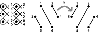
Figure 5: Analyzing column by column We begin by describing how strands are connected to each other on the left hand side of the design. In Figure 6, we show and number these strands. Note that we number the strands after they cross each other. We have also given different shadings to connected pairs of strands. We create the starting mirror graph S by placing an edge between vertices if the strands are connected to each other. Note that we have chosen a nonstandard numbering for the vertices in the graph - our reason for this will become clear in the next example. 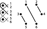
Figure 6: Starting column and mirror graph Given our restriction of horizontal mirrors between a
pair of vertical mirrors, there are only four possibilities for how mirrors
can be placed in a column: between both pairs of vertical dots, between
the upper pair of dots, between the lower (or what we will call down)
pair of dots, or between neither pair of dots. We will first look at the
result of adding a column with no mirrors to the starting column (as seen
in Figure 7). The new column permutes the six strands
with strand 1 moving to position 2, strand 2 moving to position 4, and
so on. The associated mirror permutation is n = (1 2 4
6 5 3). We can show the effect of n on the mirror graph
S.
Originally, strands 1 and 6 were connected. However, since n moves
strand 1 to position 2 and strand 6 to position 5, now strands 2 and 5
are connected.
Figure 7: The action of a no mirror column Note that the geometric effect of n is to rotate the edges (but not the vertices) of the mirror graph S by p/6 radians. This is a result of the numbering we chose for the vertices. In the next three figures, we show the effects of a column
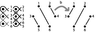
with mirrors between both pairs of dots (and associated permutation b),
the column with an upper mirror only (with permutation u), and a
column with a down mirror only (with permutation d). Note again
the geometric consequences of our numbering. For example, the permutation
d
consists of two cycles: (1 2 4 3) and (5 6). The action of d on
S
rotates the sets of vertices corresponding to each cycle clockwise one
position. So for example, the edge connecting 3 and 5 becomes an edge connecting
1 (the image of 3 under d) and 6 (the image of 5 under d).
Figure 8: The action of a both mirror column 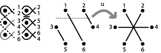
Figure 9: The action of an up mirror column 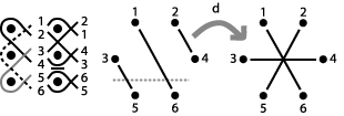
Figure 10: The action of a down mirror column At this point, we should note that we apply the permutation of each column to the mirror graph of the previous column. Figure 11 shows how the last mirror graph (which corresponds to the third column) is obtained by first applying n to S and then by applying d to the resulting mirror graph. We can also obtain the same graph by multiplying n and d and applying the resulting permutation to S. 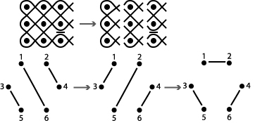
Figure 11: Composing columns While our work so far allows us to track which strands are connected as we add columns, we still need a mechanism that accounts for the last column. In Figure 12, we show the ending column and its associated mirror graph. (Note that the ending columns contains only the strand portions to the right of their crossing points.) 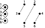
Figure 12: The ending column and graph Given a mirror graph representing the addition of several
columns, we may now superimpose the ending mirror graph. When superimposing
the graphs, we are in effect tracing a strand from left to right and connecting
it on each end to other strands. Thus, the number of connected components
in the resulting graph is the number of curves in the mirror curve design.
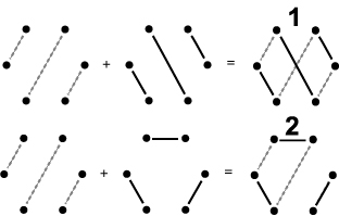
For example, the top image in Figure 13 shows the result
of superimposing the ending mirror graph on the starting mirror graph.
This corresponds to the 3 by 2 mirror plan with no additional mirrors.
By Theorem 1, the design contains gcd(3,2), or 1, curve.
The bottom image in Figure 13 shows the result of superimposing
the ending mirror graph upon the graph obtained by adding a `no mirror'
column followed by a `down mirror' column (i.e., the design seen in Figure
11). The reader can check that this design does, in fact, consist of
two mirror curves.
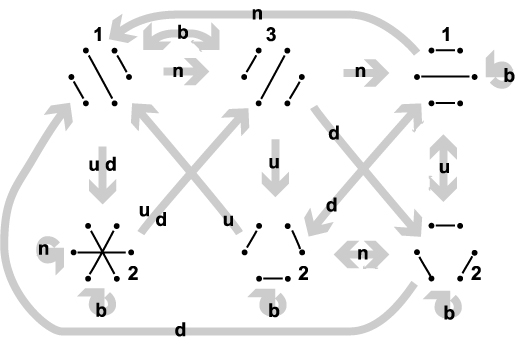
Figure 13: Superimposing E We can summarize all possibilities under our current restrictions (three rows, horizontal mirrors only, and no mirrors in the first or last columns) in Figure 14. In this figure, we show the six possible mirror graphs along with arrows showing the result of adding one of the four possible columns. Rather than superimposing the ending mirror graph, we have placed a number next to each graph showing the number of connected components if E was added at that point.
Figure 14: All possibilities in the three row case Following our assumption of no mirrors in the first column, we start in the upper left with the graph S. Following our example in Figure 11, if we add a `no mirror' column, we move to the upper middle. The addition of a `down mirror' column moves us to the lower right. Note that all mirror graphs with an associated even number are on the bottom row, while all those with an associated odd number are on the top row. Morever, permutations n and b (those corresponding to 0 or 2 mirrors in a column) do not cause a shift from row to row, while permutations u and d (those corresponding to 1 mirror in a column) always do. Thus we can conclude the following: Theorem 2: Given a 3 by n mirror curve design using only horizontal mirrors placed between vertical pairs of dots with no mirrors in the first or last columns, the number of mirror curves is even if an odd number of permutations associated with 1 mirror is used, while the number of mirror curves is odd if an even number of permutations associated with 1 mirror is used. As a consequence, mirror curve designs with 3 rows that have an odd number of columns containing an odd number of mirrors cannot be monolinear. We will now show how to extend this result to any number of rows. The m row caseWe will will keep our previous assumptions that all mirrors are horizontal and placed between vertical pairs of dots and that no mirrors are placed in the first and last columns. However, we will extend our exploration to designs built in a m by n mirror box. Our approach will be the same - we will examine the design column by column. Each column will have an associated mirror graph. Each interior column will have an associated mirror permutation. Figure 15 shows the starting column of a design with m rows, along with a `no mirror' column and the analogue of a `down mirror' column. 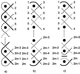
Figure 15: Three columns of a mirror design The associated mirror permutation for the column in Figure
15b) is s = (1 2 4...
2m-2 2m 2m-1... 3), while the permuation for the column
in Figure 15c) is
d
= (1 2 4... 2m-4 2m-2 2m-3... 3)(2m-1 2m).
In general, given an interior column, the associated mirror permutation
is the product p1p2...
pk
of disjoint cycles where each cycle pi has even length
and permutes a set of consecutive numbers representing the strands between
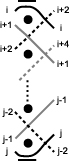
a set of two mirrors. As seen in Figure 16, each strand
has the form (i i+1 i+3... j-2 j j-1...
i+4
i+2)
where i is odd and j
is even.
Figure 16: A sample cycle After adding each column, we will create a graph G on the vertices of a regular 2m-gon. As in the 3 row case, we number the vertices by moving left to right and then down, and place an edge between vertices a and b if the corresponding strand positions are connected by a strand as of the ith column. The starting mirror graph S will always have the same form: the pairs of connected vertices will be 2 and 4, 2m-3 and 2m-1, and i and i+5 for all odd values of i less than 2m-3. Now given a column's mirror permutation p and our existing mirror graph G, let Gp be the new mirror graph obtained by applying p. We can obtain Gp by stating that vertices a and b are connected in G if and only if p(a) and p(b) are connected in Gp. We can also obtain Gp using a method similar to the 3 row case: given p = p1p2... pk where pj permutes a set of evenly many consecutive integers, for each j locate the corresponding set of vertices in the mirror graph G and rotate the set clockwise one position. Finally, our ending mirror graph E always has the same form: the pairs of connected vertices will be 1 and 3, 2m-2 and 2m, and pairs of the form i and i+3 where i is even and less than 2m-2. As before, we superimpose E and the mirror graph G for the next-to-last column. If the mirror curve is monolinear, this graph will be a simple cycle; if not, the number of graph components will be the number of curves necessary to complete the design. We can now discuss extending Theorem 2
to the m row case. Given a mirror plan, we want to find a result similar
to Theorem 2 which relates the number of curves to the
selection of columns. To start, we will first explain what all mirror graphs
look like.
Characterizing Mirror GraphsGiven two vertices a and b in a mirror graph, let us define d(a,b) as the smallest number of adjacent sides between the two vertices, when viewed as vertices of a regular 2m-gon. We can now characterize all mirror graphs. Definition: A graph is odd if it is a bipartite graph on the 2m vertices of a regular polygon where each vertex has degree 1 and given any two vertices a and b sharing an edge, d(a,b) is odd. Proposition: A graph is a mirror graph if and only if it is odd. Proof: We start by showing all mirror graphs are odd. It is easy to check that our starting graph S is odd. We want to show that if we apply a mirror permutation p to an odd graph G, the resulting graph Gp is still odd. Given a vertex a, p maps a to its adjacent neighbor in the clockwise direction or maps it across the vertical line of symmetry for the polygon. In either case, d(a,p(a)) is odd. Thus, if d(a,b) is odd and a and b are connected in G, since d(a,p(a)) and d(b,p(b)) are both odd, the vertices p(a) and p(b) are connected in Gp and d(p(a),p(b)) is odd. Thus our mirror permutations map odd graphs to odd graphs, and all mirror graphs are odd. To show that all odd graphs are mirror graphs, note that d2m-3s = (2m-3 2m) (with d and s as above). The distance between these two vertices is 2. By applying s and rotating the mirror graph, we can switch any two vertices a distance 2 apart. By composing these transpositions, we can switch any two vertices any even distance apart using mirror permutations (and not change the rest of the graph). Thus given any odd graph G, we can construct it
as a mirror graph as follows: start with S. Pick any vertex a
and its adjacent vertex b in S. If a is not connected to
b
in G, find the adjacent vertex c of a. Since
S
and G are both odd, d(a,b) and d(a,c)
are both odd, so d(b,c) is even. We switch b
and c as above. Having fixed this edge to conform with G,
we then pick any vertex besides a and c. Repeating the process,
we transform the graph into G using mirror transpositions.
Counting the componentsNow, given a mirror graph G, we want to know how applying a mirror permutation p changes the number of components when we superimpose E (or, in other words, how does adding on a column to our mirror plan change the number of mirror curves needed?) We focus our attention on a transposition q of two vertices an even distance apart (or we what will call an even transposition). Note that even though q may not be a mirror permutation, we can still define Gq as above. Proposition: The parity of components in G E differs from the parity of components in GqÈE. Proof: Suppose q = (a b) where a is connected to c and b is connected to d. In the mirror graph G, there are no other edges between these vertices. If we superimpose E, since E is odd, we may add any two edges besides the one between a and b or the one between c and d. The 5 possible cases (up to symmetry) are shown in Figure 17 with dotted lines for the edges in E (these may lead away from the vertices to show connections to some vertex not in {a,b,c,d}). Applying q to G switches the edges connecting a to c and b to d (drawn with thin solid lines) to the edges connecting b to c and a to d (drawn with thick solid lines). 
Figure 17: The cases for even transpositions In Case 1, assume that a and b are in the same component of GÈE (which must be a cycle). Switching the edges would break the cycle into two components of GpÈE. If a and b are not in the same component, then the edge switch will create one component. In Cases 2 and 3, the edge switch creates one component
out of two. In Case 4, the edge switch removes a and d from
the component, creating one extra component. In Case 5, one component becomes
two. In all cases, one even transposition changes the number of components
by one.
ConclusionsSo our question (what is the parity of curves in a mirror curve design?) reduces to the following: given a mirror permutation p, how many even transpositions does p induce? To answer this, we construct a permutation that has the same effect as p which can be written as the product of even transpositions. Given p, define p' = pa where a = (1 3)(2 5)(4 7)...(2m-4 2m-1)(2m-2 2m). The action of this permutation on a mirror graph G is to first permute the edges using p, and then to flip the edges over the line perpendicular to the line connecting vertices 1 and 3. Since all the edges in E are perpendicular to this line, the number of components in Gp' È E is the same as in Gp È E. In addition, p' moves vertices an even distance (since both a and p move vertices an odd distance). Thus if we write p' as a product of disjoint cycles, we can decompose each cycle as the product of even transpositions. To find how p changes the partity of components, we need to know if p' is odd or even (in the usual sense for permutations). The parity of p' depends on the parity of p and the parity of m (which equals the parity of a). Since p is the product of disjoint cycles of even length and any cycle of even length is the product of an odd number of transpositions, every cycle in p is odd. Thus, the parity of p depends only on the number of disjoint cycles. But the number of disjoint cycles is simply one greater than the number of mirrors in the column. Thus, we know the following: if a column has an even (odd) number of mirrors, the associated permutation p is odd (even). If we assume m is even, p' and p have the same parity. Thus a change in parity of components only occurs if p' is the product of an odd number of even transpositions, that is, if p is odd, that is, if the column has an even number of mirrors. We start with an even number of components (since the m by 2 design corresponding to S È E requires two mirror curves by Theorem 1). We have shown the following: Theorem 3: For mirror plans with an even number of rows, the parity of curves in the design is equal to the parity of the number of columns with an even number of mirrors. On the other hand, if m is odd, p' and p have opposite parity. Thus a change in the parity of components only occurs if p' is the product of an odd number of even transpositions, that is, if p is even, that is, if the column has an odd number of mirrors. We start with an odd number of components (since the m by 2 design corresponding to S È E requires one mirror curve by Theorem 1). We therefore know: Theorem 4: For mirror plans with an odd number of rows, the parity of curves in the design is opposite the parity of the number of columns with an odd number of mirrors. Note that Theorem 4 generalizes the 3 row case. While Theorems 3 and 4 do not give conditions guaranteeing monolinearity, they do provide the prospective mirror curve constructor with conditions guaranteeing non-monolinearity. Theorem 3 implies what the author calls the `even-even-even' result: a mirror curve design with an even number of rows and an even number of columns with an even number of mirrors cannot be monolinear. Theorem 3 implies the corresponding `odd-odd-odd' result. Note that both results depend on our assumptions. The
restriction that no mirrors occur in the starting or ending column can
be handled by changing S and E. However, the restriction
that all mirrors are horizontal appears difficult to remove. The introduction
of vertical mirrors would prevent the association of a permutation to each
interior column since some strands would reverse direction.
References
|