|
Art, and Physics Douglas
D. Peden
Abstract This paper
is presented as an introduction to my art
and its geometry in the union of three areas of our experience -
mathematics, art, and physics.
1. Introduction Artists invent worlds with their own laws and limitations, sometimes called style. Within this context, artists express themselves, their culture, indeed, a world we all share. Art as well as science and mathematics is a world to explore and discover that which defines us and expands the parameters of our experience. For example, in the visual arts we have various spatial approaches such as perspective, realist, cubist, atmospheric, etc. For the most part, they are all based on a Cartesian grid. Out of my art has grown a different mathematical structure based on a curvilinear coordinate system which I call Wave Space Geometry. The two basic
facets of Wave Space Geometry to be
considered in this paper are what I call
Common
Wave Space (CWS) and Interphase
Wave Space (IWS). I will
attempt to show how these geometries are used in my painting, and share
some observations and speculations concerning my work and our own physical
world.
2. Wave Space Geometry Basic Definitions
Figure 2.1
Figure 2.2
Figure 2.3 Refer to Fig. 2.1 for the following definitions. Phase
Line: a continuous line division of space.
Cross Phase Field: the crossing of two or more phase fields. Wave dimensions and wave shapes are seen in Fig. 2.2 where w is 1/2 the basic wavelength W, and a is its amplitude - the three basic wave shapes assumed are the common wave A, the line wave B, and the concave wave C. Common Wave Space (CWS) is defined by a curvilinear coordinate system. It is a wave gnid pattern formed using an X or Y phase field orientation with one field a function of the other. This is what I call a functional geometric system and should not be confused with an overlay system where one phase field is randomly overlaid on another. Interphase Wave Space (IWS) is a wave pattern formed by plotting a second generation wave field on a CWS grid. Wave
Space Equation
where each
term is drawn sequentially, Y1 and X1
indicate the primary wave field directions, the X1 field
being a function of the Y1 field to form a CWS grid configuration.
X2 is the secondary wave field taken as a function of, and interphasing
with the CWS coordinate grid. Interphasing occurs when one field track
intercepts another, going in the same direction, and returns without
crossing. The shape formed, I call a nodal
element, or node en. The other elemental shape
which is formed by two or more phase tracks crossing
each other, I call a common element ec,
as seen in Fig. 2.3. CWS is made of totally common elements;
IWS is the summation of common and nodal elements in a proportion dependent
on the interphasing geometries.
Figure 2.4 Common Wave Space (CWS)
Figure 2.5 Interphase Wave Space (IWS) An example of CWS is seen in Fig.2.4 where wY1=6, aY1=1, and wX1=6, aX1=2, or SW=G(Y16/1X16/2), written G(Y16X16/2). An example of IWS is seen in Fig. 2.5 where the X2 field of wX2=4, aX2=2 interphases with the CWS coordinate system of Fig. 2.4 in the X1 direction, the third term of Sw, The pq superscript in Sw indicates the phase position of the secondary wave on the primary wave and determines the rhythm of the interphase field as shown in Fig. 2.6.There are W possible starting positions on wavelength W; in our example, 7 out of 12 positions are shown in aG(X16) wave field interacting with a secondary X26 wave field. In Fig. 2.4 there are also 12 possible positions:W=2wX1=2×6=12. In example, Fig. 2.5, q=0 was chosen to establish the secondary X24/2 interphase wave field.Also note in the equation G[Y16(X16/2X24/2)] of Fig. 2.5 that the parenthetic bracketing indicates what is shown, and will be so in subsequent equations.
Figure 2.6 Phase Positions
Figure 2.7 Mock Axes The fourth
term of Sw, is what I call a mock
axes coordinate system; in other words, a IWS configuration used
as CWS grid. This is done by choosing an axes intersection point, i.e.,
an origin, with one coordinate starting in the pri'mary field direction,
the other starting in the secondary field direction and at each node alternating
to the other field direction, giving the continuous, divergent x,y
mock axes Xm and Ym as exemplified
in Fig. 2.7. (Notice Xm is drawn from
the upper left to lower right and Ym from the lower left
to upper right). The "layered" position of Xm and Ym
of SW, means that an Xm interphase
field, orYm interphase field,
or
both simultaneously can be plotted. Fig.2.7 shows the
single interphase track Xm2.
Figure 2.8 CWS
Figure 2.9 CWS
Figure 2.10 CWS
Figure 2.11 CWS The above examples are given to further demonstrate how Wave Space works. CWS Figs. 2.8, 2.9, 2.10, 2.11 show a progression in wave dynamics holding aX1, and Y12 constant with wX1, going from infinity to 2. Isolating
the mock axis field
Xm of Fig. 2.5,
we have Fig. 2.12. The semi-colon in equations such
as Xm: G(...) and Ym: G(...)
simply means Xm or Ym of the specific
geometry G(...). Fig. 2.13 is an extension ofFig.
2.5 space in the mock
X axis direction by
Xm2.
Figure 2.12 IWS
Figure 2.13 IWS Figs. 2.14 and 2.15 is Fig. 2.13 separated into its Xm and Ym phase fields. Fig. 2.16 is formed by extending Fig. 2.5 in both mock axes directions simultaneously.
Figure 2.14 IWS
Figure 2.15 IWS 
Figure 2.16 IWS Variation is further increased if we consider the shape of the wave w, or wave-train WT. Wave shape A was used in the previous examples. The other two basic shapes B and C, Fig. 2.3, should be noted. Figs. 2.17 and 2.18 show the B and C waves in the Fig. 2.4 CWS geometry; Figs. 2.19 and 2.20 show the B and C waves in the Fig. 2.5 IWS geometry. The symbol above the wave dimensions indicates the wave type and its orientation: ~ indicates a full wave; Ç È indicates a half wave oriented apex up or down respectively. 
Figure 2.17 CWS B Wave 
Figure 2.18 CWS C Wave 
Figure 2.19 IWS B Wave 
Figure 2.20 IWS C Wave Another approach is the compounding of wavelengths and/or wave shapes as seen in Figs. 2.21 and 2.22 in CWS, with a more complex CWS version in Fig. 2.23 and its IWS extension, Fig. 2.24. The various squiggles, as usedabove, show the specific make-up of a wave shape or wave train. 
Figure 2.21 CWS Compound Length 
Figure 2.22 CWS Compound Shape 
Figure 2.23 Compound CWS 
Figure 2.24 Compound M7S
3. Shapes in Wave Space In Wave Space, the geometry defines the space. The elements, which are shapes in themselves, as squares inCartesian space, are the increments of Wave Space. To get an idea of how shapes change from geometry togeometry. Let us take a 2×2, 4 element square, and translate it in the following two geometries: Fig. 3.1 showsthe square in three regions of the CWS geometry G(X14/4Y14/2); here, the square appears as a rather amorphousblob, one shape being almost linear in its elongation. Fig. 3.2 is an example of IWS geometry G(X12X2p22/2),which converts the Cartesian square of our space into a 4 element circular shape in Wave Space, 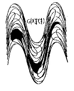
Figure 3.1 CWS 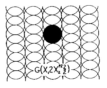
Figure 3.2 IWS 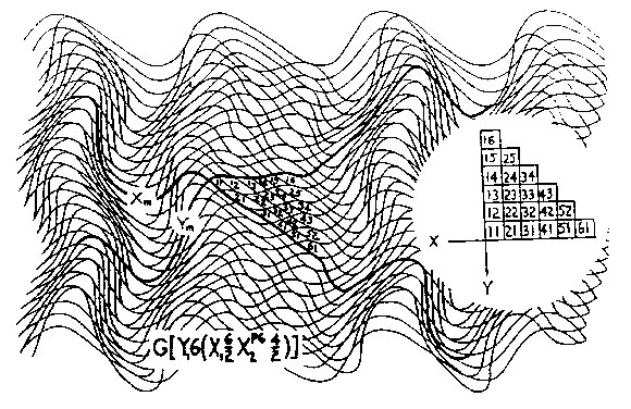
Figure 3.3 Translation What we have done is take a square from our reality and put it in a different geometric reality. In a sense, it is still a square, and would be seen as such by the inhabitants of this new geometric space; however, from our frame of reference, it has become a circle. In this kind of physicality, it begs the question: What is "true" shape? The answer would seem to depend on your frame of reference, which is true; and, in this particular case, it depends on the geometric space the object occupies. Physically and philosophically this is interesting - considering the infinity of spatial configurations possible; that is, of course, if such spatial realities exist, a speculation we will consider later. As an exercise, if we wish to translate from our Cartesian space to a Wave Space geometry, refer to Fig. 3.3. Here, we have a geometry similar to Fig. 2.5 with our mock axes arbitrarily chosen, as shown, and numbered to parallel our Cartesian grid (inset). It is now a matter of drawing a shape in Cartesian space and converting it to Wave Space, or do the reverse to see what shapes created in Wave Space look like in Cartesian space. For a demonstration, I show an imaginary character from Cartesian space, Fig. 3.4, and show it in three other geometric configurations, Figs. 3.4a, 3.4b, and 3.4c. 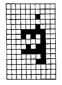
Figure 3.4 Character 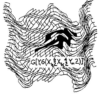
Figure 3.4a 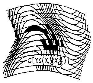
Figure 3.4b 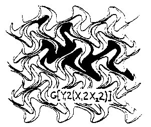
Figure 3.4c However, the idea of shapes changing outside our frame of reference is not new when we consider Einstein's illustration of a clock approaching the speed of light: From our frame of reference, we see the clock being flattened and time slowing; but, from the clock's frame of reference, evenything has remained normal. If we assume a shape to move in Wave Space, some curious things occur. A shape moving in our Newtonian (Cartesian grid) space will maintain its dimensional and geometric integrity. A shape moving in CWS will distort to a greater or lesser degree, depending on the geometry of the space it traverses; but the relationship of the elements will remain the same. However, a shape moving in IWS will not only distort, but it may fragment; that is, on an elemental level, the relationship of the elements will not remain intact. In IWS, the elements in a shape following one of the mock axes will keep a consistent relationship with one another regardless of the degree of distortion of the shape, as is shown in Fig. 3.5a. Here, we have our 4-element square following the Xm axis through a number of successive incremental changes. If the shape should follow a specific phase track exclusively, as is the case in Fig. 3.5b, some of the elements will separate (the cross-hatched figures) from their partners while passing through the nodal region; however, the square will be reformed as it passes through the next nodal region, thus following a cyclical process of fragmentation and reformation from region to region. For larger shapes comprising a vast number of elements, the individual incongruities would most likely be absorbed and seen as proportionally minor disturbances, fluctuations, or pulses. 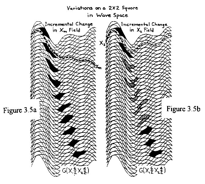
Figure 3.5a
Figure 3.5b
4. Wave Space Painting Wave space art is holistic in that the shapes, themes, rhythms, and spatial textures are defined and influenced by the geometric configuration of the chosen space. The interweaving phase fields form the individual elements, the basic building blocks of larger shapes which in themselves can build to increasingly larger wholes. The choice of the geometry to be used depends, of course, on the artist's intent. Some spatial configurations are more dynamic than others; in other words, they have a greater sense of action, or vitality, than those of a more gentle, "expressive feeling". For example, in Fig. 3.4 our Cartesian character's attitude is somewhat static; it lacks a sense of motion that is expressed by the subsequent examples. This dynamic can then be emphasized or diminished by the use of color and tone in the rhythmic structure of the painting itself. For example, red in the character might suggest a hot, aggressive, passionate individual; while a blue might express a cool, thoughtful character; and green, a calm, comfortable personality. Or such colors could be used to characterize the background environment of the painting to enhance or diminish the drama. What we are doing here is creating a world of space, color, rhythm, and texture where the shapes become living things, experiencing the trials and tribulations of the environment they inhabit - plus their own episodic changes and transfigurations. In the genre of art, my work would be considered abstract; however, the abstract components often imply literary content - that is, an abstract narrative or metaphor. In other words, I try to convey an idea or story exclusively through abstract forms, as suggested above. Indeed, our imaginary character of Fig. 3.4 could be considered venturing through the three different spatial environments and experiencing various physical and/or emotional transfigurations as implied by the geometric dynamic. Another example can be seen in my IWS painting, "Come Together", Fig. 4.1. 
Figure 4.1 IWS "Come Together" 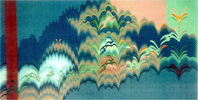
Figure 4.2 "Transfiguration" 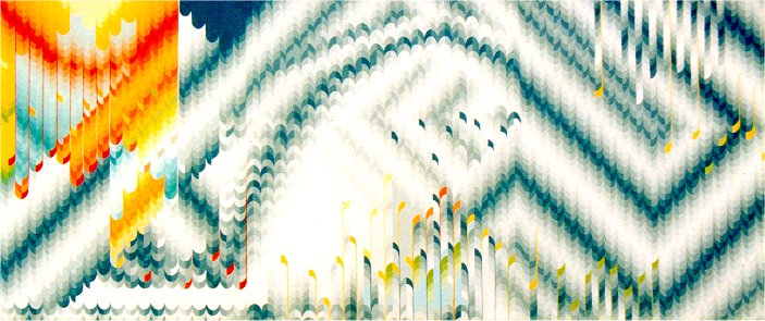
Figure 4.3 CWS "Rhapsody for 9 Notes" This painting is episodic. Beginning at the left and progressing right, through a steady rhythmic space, separate elements, or parts, come together forming a complex whole - a shape theme, or leitmotif, at the mid-point of the painting. It is subsequently transformed into a linear, dancing combination of like figures, and proceeds further through a rhythmically agitated space to the end of the painting where it is seen penetrating a vertically static, dark rhythmic color column on the verge of entering a blank, monochromatic space. It could be the end of the story or the end of a chapter. It could be "read" from right to left for a different interpretation. In any event, how the painting is approached, experienced, and interpreted is entirely up to the individual observer. Sometimes
my art is perceived as visual music; and indeed, in many cases, it is my
intent. In the context of the painting, my theme may be a single shape
as in Fig. 4.1 and 4.2; or as a group
of separate elements, Fig. 4.3, much in the same manner
of music notation in a score. The theme, is subsequently developed through
various color keys, color/tone harmonies, and thematic manipulations, i.e.,
turned, flipped, dissected, distorted, reversed, etc. - all depending
what I, the artist/composer, hope to convey.
5. Similar Worlds Exploring the worlds of my work, patterns of our day to day experience appear, suggesting structures or methodologies in Wave Space geometry that parallels our own world. I have compared on many occasions, riding the local ferry, the rippling and cross-rippling of waves with the interacting wave fields of my own studies. Perhaps you have experienced the amusing distortion of shapes in a carnival mirror, and how they change from one region to another. Some other patterns observed are flame movements, as in my painting, Fig. 5.1, "Aurora", and smoke in my study, Fig. 5.2. In a detail of my painting "Edge of Chaos" and my painting "Garden of Middle Harmony", Figs. 5.3 and 5.4, we have patterns reminiscent of gas and liquid currents, i.e., turbulence. Also in Fig. 5.4, I am reminded of the spectral patterns seen in oil slicks; I have also seen this agitated schema as a colorful, vibrating pattern on the retinas of my eyes, which apparently is a migraine headache phenomenon. 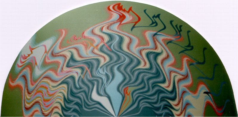
Figure 5.1 "Aurora" 
Figure 5.2 Heat Waves 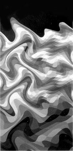
Figure 5.3 IWS Detail "Edge of Chaos" 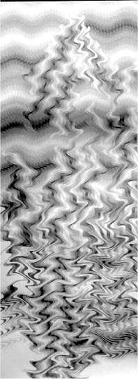
Figure 5.4 "Garden of Middle Harmony" We find interphase fields where wave patterns are damped and reenergized as in Figure 5.5. Chaos and fractal geometries are suggested in my painting "Transfiguration", Fig. 4.2. The wave track of Fig. 2.7 suggests the meander of a river. 
Figure 5.5 Phase Damping 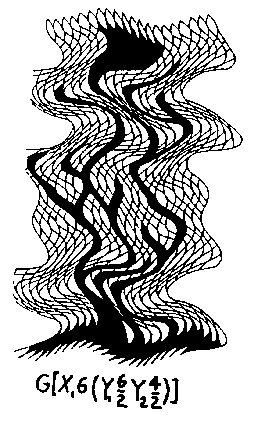
Figure 5.6 Plant Pattern 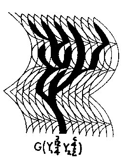
Figure 5.7 Plant Pattern 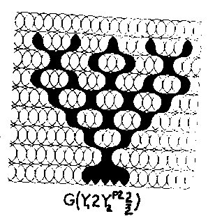
Figure 5.8 Plant Pattern By utilizing
the node as a bifurcation point, certain geometries suggest plant growth
patterns, as in Figs. 5.6, 5.7, and
5.8.
6. The Quantum Cosmic Connection Exploring the many worlds of Wave Space geometry has led me to speculate on the two extremes of our own reality, i.e., micro or quantum space and cosmic space. The basic analogy between Wave Space and the "real" world is summed up in Fig. 6.1. Here, the quantum world is viewed as a high frequency, densely packed nodular space compared to our essentially "linear", Newtonian world. This analogy seems to fit well when we consider Einstein positing a cosmic space which takes the form of a vast curvilinear geometric structure and the quantum scientists who view the microcosmos as a wave/particle paradigm of incredibly high frequencies. 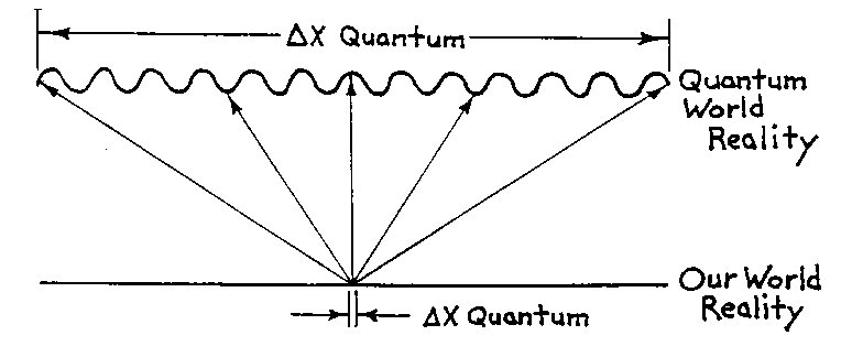
Figure 6.1 World Reality Scale 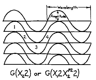
Figure 6.2 Minimum IWS Geometry Let's consider the limits of Wave Space geometry. From the previous discussion, the macro limit would be a Cartesian grid, Newtonian reality, which is our basic frame of reference. Beyond our frame of reference, in the microworld, we assume the bottom limit of Wave Space geometry. The minimum
wave configuration is w/a=2, and its spatial configuration
in IWS is given by the two equations,
Another parallel to our world is, because of the density of nodes at the quantum level, and their bifurcating factor, a microshape or particle/wave packet would have more possible paths to follow in a given distance and therefore be harder to predict its position or velocity at a given time, unless we knew the precise geometry of the space and the laws that govern it. Also, a microshape moving in a densely nodular space, as in Fig. 6.2, would be more difficult to identily due to its continual morphing from nodular to non-nodular space. The above,
of course, is pure science fiction; but even the physicists don't know
what the quantum world is like; they have a strong feeling and good reason
to believe it is quite different from our own experience. Many feel the
quantum world to be a complex paradigm of wave fields; and, even on a cosmic
scale, Einstein posits a curvilinear geometric structure. However, Einstein's
conclusion, as I understand a it is that mass, or mass as energy, interacts
with and distorts the surrounding space. In applying Wave Space to "our"
space, I have to conclude that it is the space that creates and defines
the mass, or to be more accurate, the illusion of mass. It is the interweaving
and interdependence of complex geometries that create and contribute to
the totality of reality itself.
|


